HSS
Hydro-Mechanical Swing-Clamp Unit

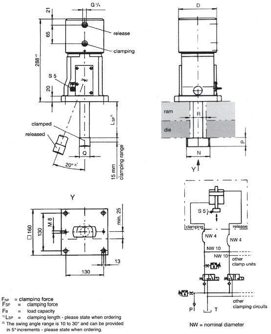
Area of application
Hydraulic swing-clamp units are designed for mediumsized and large presses exerting a force of about 500 tons upwards. Basically, they are suitable only for top die clamping.
Rigidly mounted on the press ram ledge, they require dies that have clamping edges with U-cut outs.
Mode of operation
The tie rod is swung into the clamping position via a mechanical register slot. After this swing movement (standard swing angle 20°), a double acting hydraulic cylinder transmits its clamping force, via the tie rod, to the die.
In the release process, the tie rod is released by an axial movement, and then swings back into the release position.
Movement sequence for applying the clamping force:
- Retraction of the tie rod
- Clamping stroke of the tie rod
Distinguishing features
The hydraulically operated clamping cylinder directly produces the necessary clamping force. In so doing, the hydraulic pressure must be maintained throughout the clamping process (optional equipment with non-return valves and pressure switches recommended).
Electrical control of the following functions (switches):
- Tie rod released and swung outward (S5)
- Pressure control by means of pressure switch on the hydraulic unit is advisable.
Technical data
| Switch: | 1 inductive proximity switch; p-n-p normally open contact |
| Supply voltage: | 10-30 V DC |
| Cable length: | ca. 3 m |
Max operating temperature 70°C
Advantages
- Fully automatic, and also purely hydraulic operation
- Large clamping thickness tolerance
- Compact dimensions
- High safety standard due to electrical monitoring
- Central control
- Superior corrosion protection
- Continuous pressure control possible
Construction
The clamp unit has a nickel-plated swing housing and a forged and gunmetal-finish tie rod.
The swing angle of the tie rod can be adjusted between 10° and 30°, in 5° increments as required by the customer.
To fix the clamp unit to the machine, please use four M12 bolts of strength class 8.8 according to DIN 912 (not included).