DESHV
Hydro-Mechanical Retracting Turn Clamp
Area of application
The hydro-mechanical retracting turn-clamp unit type DESHV is designed for medium-sized and large presses exerting a force of ca. 500 tons upwards. It is particularly suitable for bottom die clamping , and for inner die clamping in draw presses. It is also used for top die clamping.
The clamp unit is installed rigidly in the surface of the ram or bed. Alternatively, it may be fitted to the ram bracket.
The use of the clamp unit requires dies that have lock plates or that have clamping edges with a U-recess.
Mode of operation
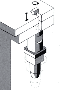
A double-acting hydraulic cylinder hydraulically initiates the clamping process by extending the tie rod outward. The tie rod is driven out to a point above the clamping edge of the die, into the clamping position. In the subsequent 90· rotation of the tie rod, a pinion is rotated by means of a toothed rod until the tie rod reaches the clamping position. In this position, an edge control bore allows the hydraulic pressure to flow to the clamping cyl inder which actuates the toggle mechanism. This hydraulically actuated but mechanically locking system transmits its clamping force to the die.
The mechanical locking effect, produced in the clamping position, is automatic and can only be released hydraulically.
Movement sequence for securing the slide:
- Driving out the tie rod to a point above the clamping edge
- 90° rotation of the tie rod
- Clamping stroke of the tie rod (release of the clamp unit in reverse sequence)
Distinguishing features
The clamp unit is fitted with the well -proven Optima toggle mechanism. In this system, the clamping force required is transmitted by mechanical components which are actuated, only during the clamping or release process, by low hydraulic pressure.
The clamping force is continuously and directly controlled by the Optima "Aktivator". For this to function there must not be any hydraulic pressure on the clamp unit. In this type of control, the clamp units are connected to the machine control system via electrical switches (precision limit switches) and, in the event of irregularities, bring the machine to a standstill.
In the idle position, the tie rod is completely withdrawn into the surface of the bed or ram, and thus protected from damage. Die changing is therefore possible without interference.
Due to the standard equipment with a pre-clamping block, die thickness tolerances up to ±0.5 mm are permitted.
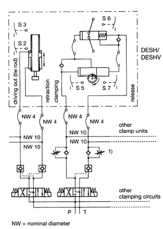
Electrical control of the following functions (switches):
- Tie rod driven out (S2)
- Tie rod retracted (S3)
- Tie rod rotated into release position (S5)
- Continuous monitoring of clamping force (S6)
- Tie rod rotated into the clamping position (S7)
Advantages
- Mechanical self-locking
- Highest degree of safety due to continuous clamping force monitoring by means of the "Aktivator"
- Central control
- Hydraulic pressure only necessary during the clamping or release process
- High mechanical load capacity
Construction
The clamp unit has a forged and gunmetal-finish tie rod.
The individual components of the toggle mechanism are made from various special alloys.Two hydraulic circuits are controlled by way of four hydraulic connections.
The clamp unit is secured by four M12 bolts of strength class 10.9 (not included).
Technical data
| Type | DESHV 100 | DESHV 200 | |
| Nominal clamping force | kN | 100 | 200 |
| Set pressure | bar | 100 | 100 |
| Max. load capacity | kN | 125 | 250 |
| Max. operating pressure (min. set pressure + 20 bar) | bar | 140 | 140 |
| Release stroke | mm (ca.) | 3.5 | 3.5 |
| Die thickness tolerance | mm | ± 0.5 | ±0.5 |
| Oil volume required (each process) clamping | cm3 | 160.5 | 247.5 |
| Oil volume required (each process) release | cm3 | 278 | 412 |
| Delivery rate per unit* | l/min. | 1.0-1.5 | 1.5-2.0 |
| Weight | kg (ca.) | 63 | 90 |
| Hydraulic connections | see drawing | ||
| Max. operating temperature | °C | 70 | 70 |
| Pressure medium | Hydraulic oil DIN 51524 - HLP (ISO DIN 51519) |
||
| Viscosity | 25 - 60 cST/40°C | ||
| Filter | 20 - 25 µm | ||
*If a pump with a higher delivery rate than necessary is used, the oil flow must be reduced
by means of flow regulating valves or oneway restrictors.
Precision position switches
| Switching function: | single-pole change-over snap-action contact |
| Supply voltage: | 250 V AC |
| Switching capability: | 2A/230 V AC
5A/24 V DC |
| Contacts: | screw connection |
| Cable lead-in: | armoured cable 9 |
For a water- and oil-tight installation, we
recommend cable screw joints, in conjunction
with a protective sleeve.

| Type | FSP [kN] |
FB [kN] |
Stroke |
A |
a1) | b ca. |
c | d | e | f | g | h | i |
| DESHV 100 | 100 | 125 | 190-150 | 500 | ±0.5 | 3.5 | 80 | 30 | 32 | 36 | 130 | 91 | 119 |
| DESHV 200 | 200 | 250 | 100-150 | 620 | ±0.5 | 3.5 | 98 | 45 | 32 | 42 | 155 | 100 | 162 |
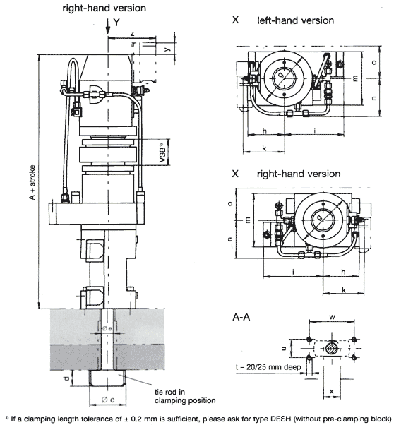
| k max |
m | n | o min |
p | r | s | t | u | w | x | y | z | Weight [kg] |
| 112 | 125 | 92 | 75 | 35.5 | 65 | 50 | M10 | 40 | 100 | 40 | 20 | 162 | 63 with stroke 90 |
| 114 | 150 | 107 | 90 | 35.5 | 62.5 | 50 | M12 | 50 | 122 | 46 | 32 | 166 | 60 with stroke 120 |